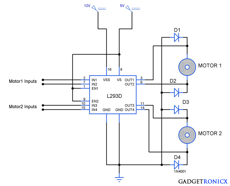
The L293D is a 16 pin IC, with eight pins, on each side, dedicated to the controlling of a motor. There are 2 INPUT pins, 2 OUTPUT pins and 1 ENABLE pin for each motor. L293D consist of two H-bridge. H-bridge is the simplest circuit for controlling a low current rated motor.
Pin No. - Pin Characteristics
- 1 - Enable 1-2, when this is HIGH the left part of the IC will work and when it is low the left part won’t work.
- 2 - INPUT 1, when this pin is HIGH the current will flow though output 1
- 3 - OUTPUT 1, this pin should be connected to one of the terminal of motor
- 4,5 - GND, ground pins
- 6 - OUTPUT 2, this pin should be connected to one of the terminal of motor
- 7 - INPUT 2, when this pin is HIGH the current will flow though output 2
- 8 - VCC2, this is the voltage which will be supplied to the motor.
- 16 - VCC1, this is the power source to the IC. So, this pin should be supplied with 5 V
- 15 - INPUT 4, when this pin is HIGH the current will flow though output 4
- 14 - OUTPUT 4, this pin should be connected to one of the terminal of motor
- 13,12 - GND, ground pins
- 11 - OUTPUT 3, this pin should be connected to one of the terminal of motor
- 10 - INPUT 3, when this pin is HIGH the current will flow though output 3
- 9 - Enable 3-4, when this is HIGH the right part of the IC will work and when it is low the right part won’t work.
Homemade Stepper Motor Controller
Why 4 grounds in the IC?
The motor driver IC deals with heavy currents. Due to so much current flow the IC gets heated. So, we need a heat sink to reduce the heating. Therefore, there are 4 ground pins. When we solder the pins on PCB, we get a huge metalllic area between the grounds where the heat can be released.
Arduino DC Motor Control with L293D Motor Driver IC. Two DC motors or one bi-polar or uni-polar stepper with up to 600mA per channel using the L293D. How to connect your “L298N Dual H. Dec 21, 2018 - One of the easiest and inexpensive way to control stepper motors is to interface L293D Motor Driver IC with Arduino. It can control both speed.
Why Capacitors?
The DC motor is an inductive load. So, it develops a back EMF when supplied by a voltage. There can be fluctuations of voltage while using the motor say when suddenly we take a reverse while the motor was moving in some direction. At this point the fluctuation in voltage is quite high and this can damage the IC. Thus, we use four capacitors that help to dampen the extreme variation in current.
$begingroup$
I've been trying to get a new 12V stepper motor to turn using the circuit below. I connected the 12V to the IC but this led to my Arduino smoking and burning out.
I'm thinking that the 12V is being pushed into the Arduino due to the common ground or my wiring is wrong. Should this circuit work be safe or will it burn out another Arduino if I connect it up again?
L293d Motor Driver Module
1 Answer
L293d Stepper Motor Controller Driver Ic Test
$begingroup$You wrote: 'In my past experience, not all GND pins need to be connected to ground'.
This is a very, very bad assumption. You are dealing with a switched high-current inductive load. You will get sharp voltage spikes during switching. GND is very critical. Take a look at the layout example from the TI datasheet below. See the crazy number of GND vias recommended for pins 4, 5, 12 and 13? And yet you have several not even connected.
These pins are probably GND for each push/pull output. By failing to GND these pins, you are forcing the GND current to go through a longer, higher impedance internal path and you are probably getting severe voltage spikes on the internal IC GND which can then cause the IC to latch up, and/or inject spikes into your digital 5V rail.